Smart speakers are becoming more ubiquitous and paired with smart home technology promise to make our homes function like something out of a 90s sci fi show, where we can do all sorts of things my just talking to our house. Unfortunately a lot of the products on offer are locked up in closed ecosystems. Smart speakers are known to send recordings back to the companies that run the eco systems they are based on, resulting in our most private moments being listened in on. As for the smart home technology, these systems are very often closed systems, are there are a few already that have been abandoned by their manufacturers, leaving the people who built them with a system that can’t be maintained or upgraded without a completely new system. The idea of rewiring a house with a system that might be abandoned by the people who made it in a few short years seems somewhat short sighted.
So, what is a geek who wants a bit of smart tech in their house to do? On the smart speaker front there is the mycroft project, and open source smart speaker system independent of the big ecosystems owned by Google, Amazon and others. Although they make their own products their software stack is completely open source (unless you choose to use it with Google’s text-to-speech engine, which is where I suspect some people get the idea that it’s ”backed by Google” from). As with most open source projects, it’s got a strong emphasis on privacy, only sharing the data with the backend that it needs to share.
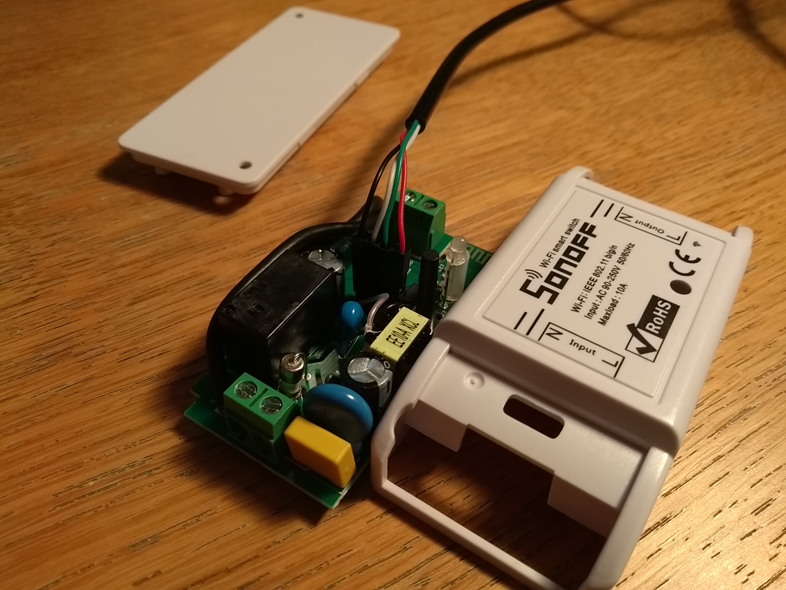
On the smart home front it is wise to go with products that some kind of open protocol. I bought a Sonoff smart switch off eBay and installed Sonoff-Tasmota on it as it supported the MQTT protocol. This would allow me to control it without being tied into any proprietary system.
So, my very modest project will be to add a smart switch to a plug-in light and build my own mycroft based smartspeaker to toggle it. So, lets get stuck in.
The smart switch
The first step was to get the Sonoff-Tasmota software installed onto the Sonoff smart switch. The Sonoff-Tasmota software builds as an Arduino application, so there are no exotic tools needed to get it on there. However you will need to add ESP8266 board definition to arduino to be able to upload the sketch to the board, so I went ahead and did that next and made sure I could build the sketch.Next I needed to do will be to solder some pins onto the board so I could connect an FTDI cable to it. I plugged the FTDI cable into the smartswitch and my PC and selected the FTDI cable as the serial port. Note that I didn’t need to have the smart switch connected to mains power in order to do this, and I would recommend against having mains power connected at this point as it adds unnecessary risk. Also, this logic level on the Sonoff is 3.3V, not 5V, so although you will probably get away with using a 5V serial cable, if you want to be super safe get a 3.3V one.
Once the software was installed I replaced the inline switch in the lamp I wanted to control with the sonoff, and connected it to my WiFi (see how here). Here in the UK we use EU colours on the wiring, so it was blue to neutral, and brown to live (I’ve never liked those colours. Maybe after Brexit we can go back to black neutral, red live #SilverLinings). I would have liked it if the switch also ground passthrough, but fortunately the lamp didn’t have a connection to the ground pin, so it was not a problem. After powering it up it shows up as a WiFi access point and I connected to it with my smartphone to add in the username and password of my network. Once it was on the WiFi i gave it a static ip address so it would not change later, went to it’s ip address in a web browser and made sure everything worked.
After I had the software installed and had it connected into the lamp I wanted to control I started looking around at how to control it. As mentioned before I was going to try and control it via MQTT, but Sonoff-Tasmota also has a web server that allows the switch to be controlled by simple REST requests (as well as providing a UI so it can be controlled through a web browser). This seemed like a simpler way forward, as it meant that I would not have to run an MQTT broker. After checking that it actually worked by firing a few requests at it from cURL it was onto the next bit.
Building the smart speaker
At the core of this speaker is an OrangePi Zero plus2. I had a few different single board computers from the Allwinner H5 family lying around, but decided to go with this one because it had exposed audio output and input connectors, making it easy to hook it up to a microphone and speakers. The first of these that I tested was the connection to the microphone. I wanted to use a simple electret microphone, but the microphone could not be plugged directly into the board. After reading up on the OrangePi I came up with this.
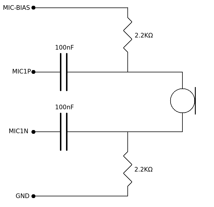
This is a simplified version of this circuit which I read about here. The main thing I did was remove some of the capacitors to ground because I thought that these would mainly affect the sound quality coming in through the microphone. As long as the smartspeaker could make out the worlds I figured it would not matter too much. As it turns out, after doing a few recording tests, it turned out that this circuit produced sound that is pretty good when listening to the voices in a room, so it was more than good enough for my purposes.
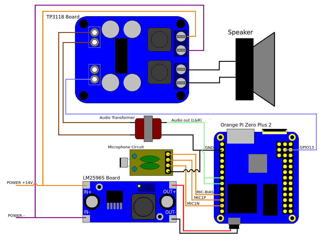
Next up was the audio output. The board I selected was a TPA3118 mono amplifier board. Because this board needs a power supply between 12V and 24V I would need to also get a power supply board to bring that down to 5V for the OrangePi. For the OrangePi power supply I bought an LM2596S DC-DC adjustable power supply board. After getting all these parts and putting them together to test them out I found that I was getting a lot of distortion similar to when I built the bluetooth boombox. Suspecting that, once again it was a ground loop issue I tried the same solution: put a transformer between the OrangePi and the amplifier. Once again this solved the ground loop issue.
The last thing to do was to figure out a way to disable the amp when it was not playing sound. The TPA3118 has a connection for a mute button, so I thought that the best way to disable the amp was to use this. After trying several different ways of connecting it to the OrangPi’s GPIO pins it turns out that all I needed to do was to take the pin *not* marked “1” from the mute connector and I was able to turn the amp on and off by toggling a GPIO pin.
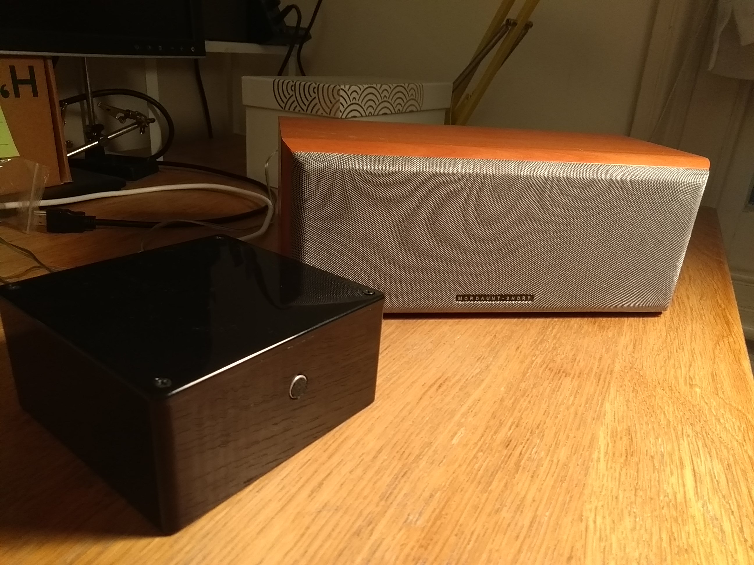
In the end the whole setup went together something like this:
And after putting this all into a project box with some external connectors for speakers and a power supply (I just used an old 14V power supply from a dead laptop) the hardware was done.
Installing the software
Next thing was to get the basic mycroft software installed. I first grabbed a copy of Armbian and installed that on the emmc of my OrangePi. I then followed the instructions here and didn’t have too much trouble. I made sure to check that Zram was installed because the OrangePi I was using had about half the RAM that the RaspberryPi that Mycroft normally runs on has. Also, I put both the swap partition onto an SD card so it wouldn’t wear out the emmc (storage like this has limited write cycles). I also reacted a specific partition for logging on the SD card, again so I could avoid wear and tear on the emmc and just replace the SD card when the time came. After this I fired up the mycroft software, registered it with their backend and everything just worked. “That was too easy” I thought to myself. I was right.
The problems that came up when I tried to automate the loading the mycroft software via systemd so that it would start as soon as the smart speaker was powered up. I had added both a service to run pulse audio, and to run mycroft after this had been started. However when mycroft had been started it was would not respond to the wakeword. Looking it at the logs I saw the message “pa_context_connect() failed: connection refused“, which indicated that it was not able to connect to the pulseaudio server. I stopped the mycroft service and run it from the command line and it worked just fine.
From here I needed to find out what was different from running it at from the command line and from systemd. I had a suspicion that it might be a difference in the environment variables that mycroft was being started with, so I made copies of the /proc/
Speaker control software
Next up I needed to put together some software to control the GPIO pin that will turn the amplifier on and off. Mycoft has a messaging system that all of its different parts use to talk to each other and it is possible for other processes to connect to it and listen to these messages and even send messages in. My plan was simply to write a small NodeJS process that would listen to the messages on the message bus and turn the amplifier on and off via the GPIO pins when the relevant events occurred. This worked well except for one problem: There were no messages that were being sent before the sound to indicate that the speaker had heard the wakeword. So, I forked the mycroft code base and added one. After this I added a few more checks to this daemon and wrapped it as a systemd service and I had control of the amp sorted.
However this wasn't quite the end of the software development as I raised a pull request to put this into the main mycroft code source code. After a little bit of discussion it was decided that this new event was not needed, and what should happen is one of the already existing events should be fired at the time I was sending mine. By the time this is out all this PR could very well be merged. I have updated teh speaker control software to use this event (the "wakeword" event.
Developing the switch skill
As I mentioned in the beginning, I decided, rather then use one of the existing skills, to develop my own skill to control the smart switch. This was because a lot of the skills for home automation seemed more geared around controlling entire systems, and I just had one light. It seemed like I would be overcomplicating things to put together an extra server just for that.
The skill is comprised of three parts, the vocab, the dialog and the code that joins the two. The vocab is a set of words that this particular skill can understand. The dialog is what the skill can say. The code will be a subclass of the MycroftSkill class and you can build phases that can be matched on by specifying patterns of vocab. This is called an Intent. So, In my “TurnLights.voc” file I had 4 phrases “turn on the light”, “turn on the lights”, “please turn on the light” and “please turn on the lights” and in the “Status.voc” file I had “on” and “off”. When I built an intent with “TurnLights” first and “Status” second I could match on any combination of those two. I can also pull out which word was in the “Status” section so I could know wether to send the “On” or “Off” command to the smart switch. I then needed to build a second intent to handle the possibility of getting the words in a different order.
And there it was, a homebrew voice activated light.
What next?
Obviously I’m going to do a bit more with this than just turn a light on and off. The next obvious thing to do will be to make it work with Spotify. There is already a skill in mycroft to do this, but the spotify player needs to be installed separately. If you buy a pre-built smart speaker from the mycroft company this will come built in, but since I did things th hard way I’ll have to do it myself. I would also like to add in the ability to ask it for the times of local trains and buses, but that will be a rather big new skill. On the hardware front I think adding an LED that gives some indication of the status of the smart speaker woudl be very useful.
But the more interesting thing for me would be to put this somewhere other than the home. Maybe put it in a car……