Last christmas I built an LED christmas tree based on WS2811 LEDs and an arduino micro and a touchscreen. At the end of that article I said that I wanted to build a WiFi based version of this controlled over WiFi, possibly based around the C.H.I.P. that I had lying around. However, after looking into the NodeMCU I thought that this would be a better candidate for this project. It’s based around the ESP8266, the same WiFi chip at the heart of the Sonoff smart switch that I used in my previous project, and I was keen to do something of my own with this chip.
The main thing I was looking to replicate was the “wifi appliance” nature of the Sonoff smart switch, the idea that this is something that you connect to your WiFi network and control. Although I’m going to use this for the Christmas tree now, this could form the basis for other WiFi controlled devices I might want to build later.
Creating the access point and web server
When the Sonoff smart switch is first turned on it will create a WiFi access point which you can connect to and enter the initial settings for it to connect to another network. This seemed like the most sensible way for me to also configure the WiFi settings for this project, so I set about putting together an access point that ran a web server that could both configure the WiFi settings and control the tree.
Setting up the initial WiFi access point was easy enough. All that is needed is to include the “ESP8266WiFi.h” file anc call “WiFi.softAP(AP_NAME)” and it will run. For the web server I used the ESPAsyncWebServer library as I liked the event driven nature of it. I wrote the one and only page of the webapp as a single web page and wrapped it in a header file to make it easy to include in the Arduino sketch while at the same time being able to separate out my html from my C code. I then added in a couple of other endpoints in the web server to manipulate the mode and the speed of the lights (which at this point just meant setting the values for those variables).
Switching between access point and connected modes
The next thing I did when trying to connect the NodeMCU to the WiFi network was to create an endpoint in the AsyncWebServer that would accept the AP’s SSID and password and just connect to the WiFi straight away. However, I did this in the function that handled the response to the web request that passed in the WiFi details and this caused the NodeMCU to crash and restart. I guessed it must be some error that gets triggered when trying to change the network configuration while there is still a TCP/IP connection active, as it would be if the web request had not finished. So, instead I put the WiFi settings into some global variables and set a flag that indicated that the WiFi settings had changed, This seemed to work well, and after adding some code to change the WiFi mode of the NodeMCU from access point mode to station mode.
Adding in the lights
I thought that adding the lights to the NodeMCU would be a simple matter of cutting and pasting the code in. However, the regular operating voltage for the ESP8266 is 3.3V, not the 5V that my WS2811 LEDs need. The datasheet does say that they can operate as low as this, but when I came to plug them into the NodeMCU they just flickered in what seemed to be a random pattern.
Using one of my old test programs from when I developed last years tree, I tried a bunch of things, but the three things that I needed to do were
- Switch from Adafruit NeoPixel to the FastLED library
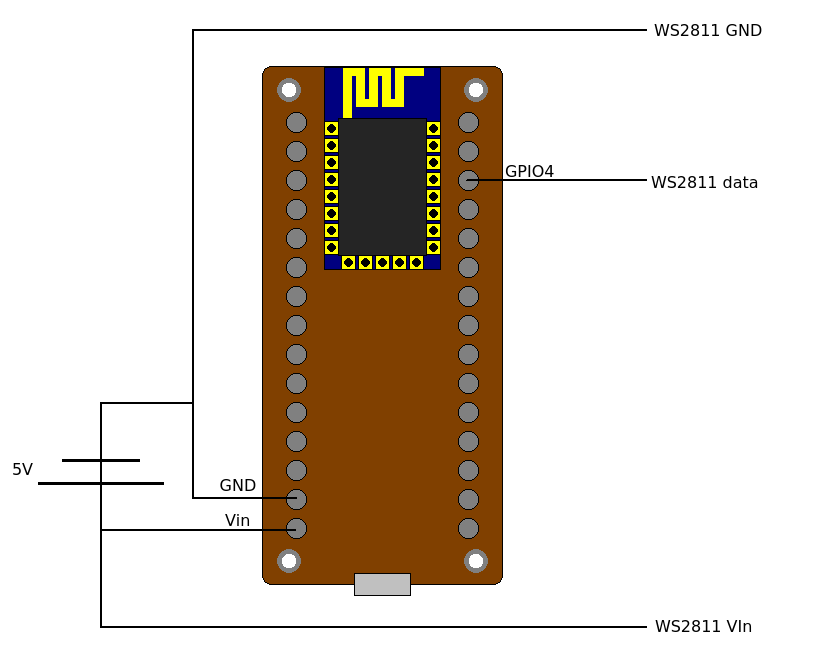
- Use GPIO 4 specifically to drive the LEDs.
- Not draw power for the lights from the NodeMCU’s, use an external power supply
The last one needed a bit of clarification. Although the NodeMCU has a Vin pin that has 5V on it coming from the USB power supply, and attempt to draw power from this will result in erratic behaviour from the NodeMCU. However, if this is the pin that is being used to power the NodeMCU it appears that you can attach other things to it, provided that the 5V power supply attached to it can handle the load. Presumably this is a problem with the voltage regulator taking the USB 5V down to 3.3V.
So, the final circuit looked like this.
After I had fixed the power issue the lights were flashing I moved all of this code into the NodeMCU program using the mode and speed set from the web app and then moved onto the next step.
Finding it on the network
One of the things I really didn’t like about the process of getting the Sonoff connected to the network was that there is no way to find it. Once you have connected it you either need to check in your WiFi router to get its IP address, or you need to just try every IP address on your network to find it.I thought a better way to find the tree would be to send a broadcast UDP packet from an app that would send a packet to a particular port to all devices on the network at once. Then the NodeMCU could reply with its own IP address and the app would know that it had found an appliance it could talk to and would present this to the user. Selecting the tree from the list of things found in the app takes the user stright to the web page served from teh NodeMCU used to controll it.
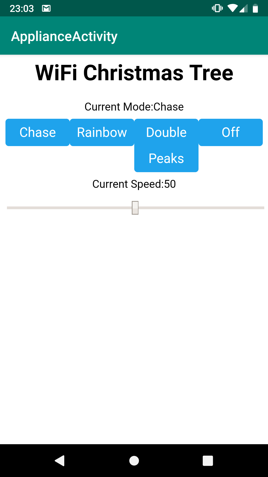
This worked really well, and I have put the Android app onto github and will probably use this technique in any future projects that can be controlled over the network.
Next year’s presents
The main objective of this project was not so much to build another Christmas tree, but to see how easy it would be to build a WiFi appliance that could be connected to a WiFi network and then managed and controlled through that network via a smartphone. I think with what I have put together for the NodeMCU, and my ApplianceFinder app I have been able to do this quite successfully, and requiring only the level of technical knowledge that the average phone user would possess. Also if I get chance before Christmas I’ll make a mycroft skill for it so I can control this thing from my smart speaker.
Oh, and Merry Christmas everyone.